>>>Security & Protection
Brand Name Мастер КИТ
Model Number Nm4511


The device is designed to adjust the brightness of incandescent lamps operating from DC power up to 600 W (50A). Using powerful lamps as sofits during video video, the regulator will allow you to set the necessary illumination. The increased frequency of regulation completely eliminates flicker of video recording and significantly reduces eye fatigue. By adjusting the brightness of the portable car lamp, you can set the necessary illumination during repair or rest and reduce the discharge of the battery. The proposed device can be used as a power regulator of various heaters operating from DC voltage, such as car seat heaters or motors. The device can be used to regulate rpm of powerful DC motors. The application of modern элементной base allowed improve efficiency controller up to 99% and maximum reduce the dimension of device.
Technical specifications
Power supply voltage:
6... 24 B
Maximum load current:
50 A
Efficiency, at least:
99%
Adjustment range:
0... 100%
Operating frequency:
500Hz
Consumption current, no more than:
1,5 mAh
PCB size:
40 х35mm
Weight
44
Instructions
Summary Table of Power regulators master kit
Instruction
More information
The brightness regulator of the filament lamps is made on the basis of a latitude-pulse regulator. The application of the dual operating amplifier DA1 LM358 allowed to implement the generator with latitude-pulse modulation with a minimum number of parts. The generator, made on one of the operating amplifiers, ensures the independence of the operating frequency from the power supply voltage and the duration of the output pulse. As an output power key, the field transistor VT1 irf3205. Small resistance open channel transistor (RDS(ON) = 0,008 Ohm.) enables the use of a transistor without heat sink when switching to 10... 12 A (when power load up to 100... 150 W). Much attention was paid to the tracing of the PCB when designing. Incorrectly performed tracing of printed conductors of powerful pulse devices can lead to their incorrect operation or to complete inefficiency.
If the engine is used as a load, it is desirable to finalize the scheme:
-In order to avoid whistle winding of the engine it is desirable to increase the frequency of PWM regulator to 22 kHz, for which it is necessary to replace the categories of capacitors C2 C2 C2 C2
-To avoid overheating of the key transistor due to reverse current pulses in the engine, it is desirable to put a Schottky diode parallel to the engine on the corresponding current, for for.
Circuit
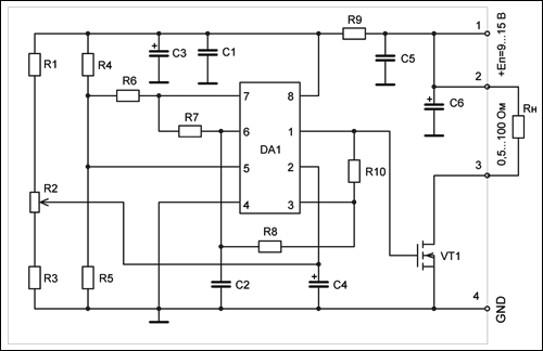
Diagram
Order Assembly
1. check the complete set according to the items list.
2. formula component conclusions (chipset, transistor resistors and capacitors). Distance between pins for constant resistors and 5mm capacitors. Please note that resistors are installed vertically.
3. install all components (except for R1 AC resistor).
4. set variable resistor R1. Attention! Variable resistor is installed on the part of soldering elements. The PCB provides a place to install another type of AC resistor.
5. gently rinse the board from flux residues with ethyl or isopropyl alcohol. Do not allow liquid ingress (flux, alcohol, etc.) into the case of AC resistor R1.
Maintenance
With a current of more than 5A, you need to install a radiator, and also you need to strengthen the tracks with a copper wire (The Wire section is selected depending on the current strength)) At a maximum current of 50A, the radiator area shall be at least 600 cm2.
